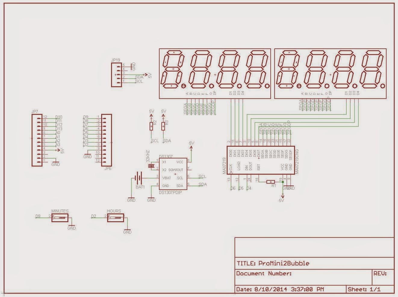
Instead, I preferred to use the expensive ($8+) LED driver MAX7219. Luckily, I got mine a long time ago as free sample from Maxim, and this was my chance to use it. As one can expect, the "double bubble" clock can display the seconds, plus the date and day of the week.

Below are the 2 bubble clock versions side by side. Both are ProMini shields, so ProMinis get plugged on their backs. I designed them to stand by themselves with the electronics exposed and on the open, as shown in this post. I am not sure if this is a good idea, but designing (or finding) an enclosure seems even a bigger challenge.

The sketch, included below, uses the LedControl library (communicates with MAX7219 through SPI).
#include "LedControl.h"
#include "Wire.h"
#include "DS1307.h"
#define PIN_DIN 12
#define PIN_CLK 11
#define PIN_LOAD 10
#define PIN_BTN_SETHOUR 2
#define PIN_BTN_SETMIN 9
int hour, minute, second;
// read time from DS1307 at intervals;
#define MAX_TIME_READING_COUNTER 1000
long timeReadingCounter = MAX_TIME_READING_COUNTER;
LedControl lc = LedControl(PIN_DIN, PIN_CLK, PIN_LOAD, 1);
void setup()
{
// MAX72XX is in power-saving mode on startup, we have to do a wakeup call;
lc.shutdown(0,false);
lc.setIntensity(0,8);
lc.clearDisplay(0);
pinMode(PIN_BTN_SETHOUR, INPUT_PULLUP);
pinMode(PIN_BTN_SETMIN, INPUT_PULLUP);
}
void displayTime()
{
// hours;
lc.setDigit(0, 4, hour/10, false);
lc.setDigit(0, 5, hour%10, false);
// minutes;
lc.setDigit(0, 7, minute/10, false);
lc.setDigit(0, 0, minute%10, false);
// seconds;
lc.setDigit(0, 2, second/10, false);
lc.setDigit(0, 3, second%10, false);
// delimiters (optional);
lc.setChar(0, 1, ' ', true);
lc.setChar(0, 6, ' ', true);
}
void loop()
{
checkButtons();
timeReadingCounter++;
if (timeReadingCounter > MAX_TIME_READING_COUNTER)
{
getTimeFromRTC();
displayTime();
delay(5);
timeReadingCounter = 0;
}
}
void getTimeFromRTC()
{
int rtc[7];
RTC_DS1307.get(rtc, true);
// check to avoid glitches;
if (rtc[DS1307_MIN] < 60 && rtc[DS1307_HR] < 24 && rtc[DS1307_SEC] < 60)
{
second = rtc[DS1307_SEC];
minute = rtc[DS1307_MIN];
hour = rtc[DS1307_HR];
}
}
void setTime(int hh, int mm, int ss)
{
getTimeFromRTC();
RTC_DS1307.stop();
RTC_DS1307.set(DS1307_SEC, ss);
RTC_DS1307.set(DS1307_MIN, mm);
RTC_DS1307.set(DS1307_HR, hh);
RTC_DS1307.start();
}
void checkButtons()
{
// increment hours and minutes;
if (LOW == digitalRead(PIN_BTN_SETHOUR))
{
hour++;
if (hour>23) hour = 0;
setTime(hour, minute, 0);
delay(400);
}
if (LOW == digitalRead(PIN_BTN_SETMIN))
{
minute++;
if (minute > 59) minute = 0;
setTime(hour, minute, 0);
delay(400);
}
}
Since it's a shield, the board requires a ProMini. The device takes about 50mA.
Schematic and board are shown below.

I shared the PCB layout at OSH Park, so anyone can make their own.


Great work on the shield.
ReplyDeleteIs there any chance you have some left (for the 4 digits version)? I was just starting to play with my max7219 and the bubble display and thought "someone must have made a pcb foir it!".
Sorry Yair, I don't have any left. I wish I could buy them all (as somebody else did) from Sparkfun, when they were $2.95.
DeleteCan you tell me the resistor values used? Thanks.
ReplyDeleteFrom old photos of the kit, it looks like all 3 resistors were 4k7.
Delete