Thursday, December 25, 2014

XBee-fy the ESP8266 WiFi module

With the new ESP8266 module, adding WiFi to any Arduino project became a lot cheaper.
This module has a serial interface; therefore it only requires connecting 4 pins: Tx, Rx, 3V3 and Ground, as shown in this image.

A few peculiar facts about ESP8266:
  • default serial baud rate is 57600; since this rate is too high for SoftwareSerial library, a hardware port should be used;
  • requires 3V3 for power and level shifting for Rx signal (5V to 3V3);
  • physical interface is a 2x4 pin male header;
  • firmware can be upgraded to a version that allows 9600 baud rate;
  • can be used either as client or server.
The first two characteristics makes it a perfect candidate for a module with an XBee footprint, as is WiFly, for example.

It took me about half an hour to do it, following these steps.
  1. cut a piece of 2-mm perfboard to the XBee dimensions;
  2. solder two 10-pin the 2-mm-spaced male headers on the sides;
  3. desolder (using wick) the 2x4 header;
  4. mechanically attach the header-less ESP8266 module to the XBee perfbord, by soldering 4 pins into the corner holes, aligned with holes in the perfboard;
  5. wire the pins 1, 2, 3 and 10 of the Xbee-type module to pins Vcc, Tx, Rx and Gnd of the ESP8266 module respectively.

And now a few photos. Start with these (XBee shown for comparison purpose):


to make this:


Then plug it any Xbee socket, like one on Wise Clock 4:


or Adafruit XBee adapter:


Hopefully now more people can try adding new WiFi features to their Wise Clocks without breaking the bank (paying $35 for WiFly).

Sunday, December 14, 2014

M4 receiver backpack for reliable wireless remote control

My investigation into the failure of the M4 receiver remote controlling my Wise Clock 4 concluded with the need to add a step-up converter. The Sure 1632 display makes the input voltage drop sometimes below the absolute minimum of 4.5V required for the M4 module to work properly. It's not the noise (spikes) in the 5V power, nor the interference on 315MHz.

I designed a simple "M4 receiver backpack" that uses a DC-DC step-up converter to ensure a 5V power for the M4 receiver module. The board supports 2 different kinds of converters, one from ebay (red in the photo below), the other from tindie (made by BBtech, black in the photo).


The backpack can be used, by default, without the step-up converter if the voltage is steady at around 5V. (A trace-jumper must be cut when a converter is added.)

The wireless remote pair of 4-key fob transmitter and receiver module is sold by Adafruit or vendors on ebay.

The assembled board wired to Wise Clock 4 is shown in the photos below. Note that only 3 out of 4 buttons on the remote have a function on the clock. Each button press could light up a (optional) LED on the receiver board for visual confirmation.


A new design of the Wise Clock 4 board should probably feature a header for plugging in the receiver module, otherwise the back of the board will show a bunch of ugly wires.


This M4 receiver backpack could be used for adding remote control to other devices with buttons, especially when these buttons are hard to access (due to enclosure design constraints), or hidden (for aesthetic purpose). One example that comes to mind is an oscilloscope clock fully enclosed in transparent acrylic; drilling holes for the buttons would require some design stretches.

Schematic and board layout are shown below.


The M4 receiver backpack would be also suitable for hacking old commercial alarm clocks. Please let me know if anyone is interested :)

Sunday, November 30, 2014

It happened again

Once again, Sure Electronics modified their 32x16 3mm LED display, and this time not only cosmetically.
The two 16-pin shrouded male connectors have been replaced with 10-pin connectors. And the worst thing is that the display now requires 12V for power! Maybe these new displays are intended for use in vehicles powered by 12V batteries. Or maybe designers thought a 12V power source is easier to access than a 5V one. In any case, the display has an on-board DC-DC switching regulator (with XL4013) to make the required 5V.

For someone who needs to replace the older model with the new one, the immediate consequences are:
  • the connector between the driver board (e.g. Wise Clock 4) and the display won't work; connections must be re-wired, probably using an adapter cable;
  • either supply 12V to the board through the connector, or hack the display by soldering the 5V wire directly to the board (see the photos);
  • the holes won't align anymore.

The good news is that the display is electrically compatible with the old one. With the correct re-wiring, the display should work without any software changes.

The following photo shows the testing of the display with the Wise Clock 4 board (and it works just fine).


The display has a series of rail bars that can be used for soldering the 5V power wire, as shown below.


A new design based on this display should (or must) use a 12V power supply. Powering from the USB is not an option any more. This would require a re-design of the Wise Clock 4 board as well (USB connector would be useless now; the FTDI cable won't be able to power the display).

Saturday, November 29, 2014

From the mailbox (with software updates)

New software for the Bubble clock from MikeM:
I have the bubble LED shield working with the DS1337 RTC & LiPo shield.  I have it alternating the display with the battery voltage every 2 seconds right now.  I don't have a voltmeter handy, so I haven't verified what is displayed with actual voltage.  It started fully charged at 4.2v and has now dropped to 4.1v.  It should start blinking at 3.45v, and go to sleep at 3.3v.
I started with your original bubble sketch from the blog posting, but then had to remap all the display pins from the schematic.  The current version of the SevenSeg library doesn't match your code, so I had to make some adjustments.
I also changed the SevenSeg library code to even out the brightness.  It looped through all the segments and turned on each appropriate digit, then delayed and turned everything off.
I changed it to loop through all the digits, turning on each appropriate segment.  Once all the appropriate segments are lit, it turns on the current digit, delays, then turns everything off, then moves to the next digit.  With the previous method some segments were bright and some dim, depending on what was displayed on the other digits.
I also changed the SevenSeg library to not blank leading digits.  It now displays 01.36 for 1:36 AM.  I left it as a 24-hour clock.  I can only display a decimal point, not a colon.
Thanks again Mike!

From ScottH, another version (HDSP.ino only; the rest of the files are unchanged) of the HDSP clock sketch adds scrolling of the time and date and improved setting. Thanks Scott!

From DaveC [on the HDSP clock]:
Here are the pictures.  Hope you find it interesting, unique at least.   There is a slide switch in the back with selections Solar charge, USB charge, USB run (the default mode of the kit), and battery run where you press that button on the front to turn on and display the time.   I used a solar/USB  charge board from Adafruit as I am no EE to figure out how to charge a battery from solar and USB with all of the correct regulated voltages etc.  The case is made from corian and in the top view those speckles are a kind of metallic flake in the corian, the center band is pure black. 


From EricL [on the HDSP clock]:
We got the package last week and my 13 yr-old grandson and I soldered it together and powered it up. Works perfectly!! Then I got your Arduino code for it and programmed it with a flashing ':' between hours and minutes and between minutes and seconds. Then I set the date in the RTC and changed the code again. Now it shows the date for 2 seconds every minute. Nice! Thanks for a great project!

From GregoryK [on the HDSP clock]:
Your kit is fantastic. Simple but well thought out. Thanks for bringing it to the market!
I would like to use it in one of my classes at Stanford as an "intro to soldering" and "intro to Arduino hacking" (they already will be familiar with the Uno) project.

From IvanS [on Wise Clock 4]:
Thank you Florin for the very thoughtful and entertaining  gift. Anything based on electronics is always interesting to me. We have been reading the famous quotes all day. It was a pleasure to meet you [...]

"Double Bubble Clock" shield for ProMini

I could have added a second bubble LED display to my "bubble clock" by connecting the anodes for the 4 new 7-segment digits to the only 4 pins left available: D0, D1, A6 and A7.
Instead, I preferred to use the expensive ($8+) LED driver MAX7219. Luckily, I got mine a long time ago as free sample from Maxim, and this was my chance to use it. As one can expect, the "double bubble" clock can display the seconds, plus the date and day of the week.


Below are the 2 bubble clock versions side by side. Both are ProMini shields, so ProMinis get plugged on their backs. I designed them to stand by themselves with the electronics exposed and on the open, as shown in this post. I am not sure if this is a good idea, but designing (or finding) an enclosure seems even a bigger challenge.


The sketch, included below, uses the LedControl library (communicates with MAX7219 through SPI).

#include "LedControl.h"
#include "Wire.h"
#include "DS1307.h"

#define PIN_DIN          12
#define PIN_CLK          11
#define PIN_LOAD         10
#define PIN_BTN_SETHOUR  2
#define PIN_BTN_SETMIN   9

int hour, minute, second;

// read time from DS1307 at intervals;
#define MAX_TIME_READING_COUNTER  1000
long timeReadingCounter = MAX_TIME_READING_COUNTER;

LedControl lc = LedControl(PIN_DIN, PIN_CLK, PIN_LOAD, 1);

void setup()
{
  // MAX72XX is in power-saving mode on startup, we have to do a wakeup call;
  lc.shutdown(0,false);
  lc.setIntensity(0,8);
  lc.clearDisplay(0);
  pinMode(PIN_BTN_SETHOUR, INPUT_PULLUP);
  pinMode(PIN_BTN_SETMIN,  INPUT_PULLUP);
}

void displayTime()
{
  // hours;
  lc.setDigit(0, 4, hour/10, false);
  lc.setDigit(0, 5, hour%10, false);
  // minutes;  
  lc.setDigit(0, 7, minute/10, false);
  lc.setDigit(0, 0, minute%10, false);
  // seconds;
  lc.setDigit(0, 2, second/10, false);
  lc.setDigit(0, 3, second%10, false);
  // delimiters (optional);
  lc.setChar(0, 1, ' ', true);
  lc.setChar(0, 6, ' ', true);
}

void loop()
{
  checkButtons();
  timeReadingCounter++;
  if (timeReadingCounter > MAX_TIME_READING_COUNTER)
  {
    getTimeFromRTC();
    displayTime();
    delay(5);
    timeReadingCounter = 0;
  }
}

void getTimeFromRTC()
{
  int rtc[7];
  RTC_DS1307.get(rtc, true);
  // check to avoid glitches;
  if (rtc[DS1307_MIN] < 60 && rtc[DS1307_HR] < 24 && rtc[DS1307_SEC] < 60)
  {
    second = rtc[DS1307_SEC];
    minute = rtc[DS1307_MIN];
    hour   = rtc[DS1307_HR];
  }
}

void setTime(int hh, int mm, int ss)
{
  getTimeFromRTC();
  RTC_DS1307.stop();
  RTC_DS1307.set(DS1307_SEC,  ss);
  RTC_DS1307.set(DS1307_MIN,  mm);
  RTC_DS1307.set(DS1307_HR,   hh);
  RTC_DS1307.start();
}

void checkButtons()
{
  // increment hours and minutes;
  if (LOW == digitalRead(PIN_BTN_SETHOUR))
  {
    hour++;
    if (hour>23) hour = 0;
    setTime(hour, minute, 0);
    delay(400);
  }
  if (LOW == digitalRead(PIN_BTN_SETMIN))
  {
    minute++;
    if (minute > 59) minute = 0;
    setTime(hour, minute, 0);
    delay(400);
  }
}

Since it's a shield, the board requires a ProMini. The device takes about 50mA.
Schematic and board are shown below.


I shared the PCB layout at OSH Park, so anyone can make their own.

Thursday, October 23, 2014

OLED clock with Pacman mode

This large 2.42" OLED I2C module can be used as a replacement for the smaller 0.96" display for which I originally designed the ProMini OLED clock shield. It is built around the same SSD1306 chip, and it only comes in yellow (for now).

MikeM wrote this great Pacman clock sketch for it (available for download here), shown in the video below.


To display on the OLED, Mike used U8glib graphic library. Initially tested on the 0.96" OLED, the sketch froze after some time, for a yet to be explained reason. The same sketch works perfectly with the 2.42" display. Mike spent a lot of time trying to figure out if the culprit is software (bug in the U8glib) or hardware.
(Any feedback on this issue is greatly appreciated.)

The clock can also display the time as HH:MM:SS on the whole screen, as shown in the photo below, also courtesy of Mike.


My next step would be to design an enclosure for it. For that I will probably need some more help :)

Update Nov 29, 2014, from MikeM:
A lot of credit goes to MikeR, I took the Tetris and Pacman faces from his sketch and adapted them for the OLED shield.  The Pong code is modified from the WiseClock sketch.  The digital, analog, and QR code faces are mine, although I did use a QR code library I found.  I did credit MikeR inside of the code.

Sunday, September 28, 2014

Blast from the past

MikeM sent this photo he took of the guts of the revolutionary-at the-time Sinclair Black watch beside the Bubble clock shield.


Mike also noticed odd behaviour of the clock shields (both bubble and OLED) when powered from the 3.7V LiPo battery (as shown here). After a while, the RTC returns bogus time. A quick check of the DS1307 datasheet (page 3) confirmed my suspicion:
When 5V is applied within normal limits, the device is fully accessible and data can be written and read. When a 3V battery is connected to the device and VCC is below 1.25 x VBAT, reads and writes are inhibited. However, the timekeeping function continues unaffected by the lower input voltage. As VCC falls below VBAT the RAM and timekeeper are switched over to the external power supply (nominal 3.0V DC) at VBAT.

Therefore, if one really wants the clock(s) powered from LiPo, a step-up converter must be used.
Another solution is to replace the DS1307 with the (almost) pin-to-pin compatible DS1337. This one does not provide support for a backup battery, relying instead on the main power (Vcc). Which shouldn't be a problem with a LiPo. The software would need to set the ATmega328 to sleep when the LiPo voltage drops under a certain (e.g. 3.5V) value. Once the display goes blank, the user should know it's time to charge the battery. (Note that another nice feature of DS1337 is alarm capabilities.)

I actually went through a similar exercise in the past, when I had to pick DS1337 over DS1307, for the exact same reason, but I forgot about it.

Conclusion: do not use DS1307 when the design calls for powering from 3V3 or directly from 3.7V LiPo.

Wednesday, September 24, 2014

Adding RF remote control to Wise Clock 4

Nick asked me once about adding remote control to his mega wise clock, similar to those pictured here (or any wise clock that may hang on a wall, for that matter). An obvious way to quickly and easily do this is by wiring the "simple RF M4 receiver" from adafruit to the 3 buttons of the Wise Clock. This 315MHz receiver module works in conjunction with the 4-button keyfob, also from adafruit. Note that the receiver comes in 3 flavors: momentary, toggle and latch. The one that "simulates" the touch buttons is the momentary one, hence the "M4" in the name (momentary, 4 outputs).

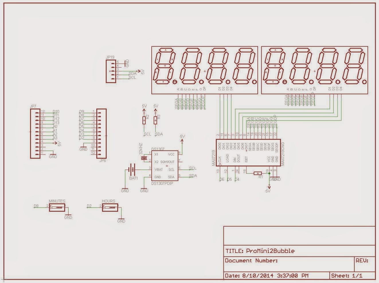
The schematic I used to connect the receiver module to the Wise Clock board is shown below.


I tested it and it works fine. Almost always :)
That is, ALWAYS when the display is not plugged in the clock board, NEVER when the display is connected. Which led me to conclude that either the display emits in the 315 MHz band (interfering with the receiver module; which it didn't; I checked by shielding the receiver in a metal case, wire antenna out), or it gets the power too dirty for the receiver.

An oscilloscope would have quickly answered my question. But since I don't have one, I tried all kinds of power adapters (from the fake-$1-on-ebay iPhone ones, to genuine 2A Samsung), up to batteries (4xAA). Incredibly, only the latter did the trick. Again, to emphasize, this is ONLY when the 3216 display is connected.

Below are some photos of the setup.


Note how the receiver is powered directly from the AA batteries. There is a common ground with the clock board though (black wire).


The LEDs are not mandatory, I added them just for visual feedback. They light up when either the board's or keyfob's buttons are pressed.

In any case, using the batteries to power the module is just to prove that this solution works. To be practical, I should add a DC-DC step-up voltage converter. According to the PT2272 datasheet (the chip on the M4 receiver), the module can be powered from 5V to 10V. I am not sure a boost converter would work in this case, unless it outputs really clean voltage, but it's the only practical solution I see at the moment.

Once I have this figured out, I plan on designing a small add-on board. The receiver module will plug into this add-on board, which will be connected to the Wise Clock's board through 5 wires.

As always, feedback (and help) is greatly appreciated.


PS I forgot to mention that I tried filtering the power with capacitors, up to 1000uF, with no success. (The 2-pin female header where the battery wires are plugged in were initially used to insert different capacitors.)


Saturday, September 6, 2014

HDSP clock mod displays proverbs

MikeM ported this "proverb clock" to HDSP clock. I did not have a chance to try the code myself yet (I am out of displays at the moment), but he vouches for it:
The proverb code is in place and working well.  I created a simple menu, accessed by pressing the hour and the minute buttons at the same time.  I have a 12 hour/24 hour selector, brightness selector, and Proverbs on/off selector.
Grahame Marsh's original proverb list was all in upper-case because his VFD displays only handled upper-case.  I've regenerated the compressed proverb list after changing it to only capitalize the first letter.  To do more than that I'd have to proof-read each of the 770 proverbs and find all the proper nouns to capitalize.  Capitalizing the first letter as a compromise doesn't look bad.  It helps the eye find the start of the word while the proverb is scrolling.

Mike also 3D-printed this stand, re-scaling to 72% this iPhone dock from thingiverse.

Thanks Mike!

P.S. I was a backer for this kickstarter clock. I like the way it turned out. It looks pretty similar to my old BookClock, using a similar 32x8 display, but centered around a Raspberry Pi (instead of just a simple Arduino), the main reason being the need to access the internet (to get the time, quotes, personal financial data etc). The only issue with this clock is that it is not open source (well, at least not the software). But I am sure an equivalent functionality can be achieved with a WiFi module (e.g. the cheap and famous by now ESP8266) connected to BookClock's Arduino.

Saturday, August 30, 2014

ProMini clock shield with OLED display

Yet another ProMini clock shield kit, this time featuring a 128x64 I2C OLED display.


The kit can be purchased with or without the OLED display (I prefer you buy the OLED on your own, for example this excellent one from miker).

  US$30, includes OLED display, free shipping to North America

  US$16, OLED not included, free shipping to North America

The kit includes:
  • PCB
  • DS1307 SMD
  • 32kHz crystal
  • CR1220 coin battery
  • battery holder
  • optional: I2C 128x64 OLED display (blue or white)
  • tactile switch (2x)
  • resistor 10k (2x)
  • machined male pins


The PCB was designed to accommodate I2C OLED displays with the 4-pin header configured either as VCC-GND-SDA-SCL or as VCC-GND-SCL-SDA.

The OLED clock can also be powered from the same LiPo battery shield for ProMini, as used in the bubble clock. To minimize current consumption (beside disabling the ProMini on-board LEDs), the processor can be awaken from sleep at the push of the "hours" button (on D3).

Schematic and board layout are shown below.


The OLED clock could show the time in many different ways, including Pong mode (sketch adapted from miker), analog clock mode, digital clock mode (sample sketches to be provided soon).

ProMini clock shield with 7-segment bubble display

Update May 6, 2016: This kit is no longer offered until I get a new batch of QDSP-6064 displays (whose price seem to have jumped considerably).

This clock was designed as a ProMini shield. It comes as a mostly-SMD kit, based on DS1307 with battery backup and the QDSP-6064 7-segment LED "bubble" display.


The kit includes the following:
  • PCB
  • QDSP-6064
  • DS1307 SMD
  • 32kHz crystal
  • CR1220 coin battery
  • battery holder
  • 330 ohm resistor 0805 (8x)
  • tactile switch SMD (2x)
  • machined female pins


The assembled clock can be fitted with a LiPo battery shield for ProMini, as shown in this post (source code also provided there).
The current draw (measured at 20mA with an unmodified ProMini) can be minimized by removing the 2 LEDs on the ProMini board, as well as dimming the 7-segment bubble display through software (SevSeg library). One other way of maximizing the LiPo battery life cycle is by waking the clock from sleep mode at the press of the "minutes" button (on D2).

Schematic and board layout are shown below.


Back in "business"

Just returned from my vacation in Paris. Hotel de Crillon was closed for renovations, Ritz had limited availability also due to renovation, so I had to settle for The Peninsula ;)


Here are a few impressions and observations, while still fresh.
  • taxis only take cash; ride from the airport to Paris center is about 60 euro and takes about 50 minutes;
  • the lowest cost Starbucks coffee is twice as expensive as here, at about $4.5 (3 euro), but still a lot cheaper than the "cafe creme" at Les Deux Magots or Cafe de Flore;
  • cheques are still used for grocery shopping (!);
  • the fixed air conditioning units (installed outside the windows) are probably not allowed, since they would really spoil the beauty of the buildings; posters are also forbidden, though I saw some "pixel art" placed high (that is, hard to remove) on some buildings;


  • one can actually live on and retire from a job as waiter or hotel concierge;
  • tipping in restaurants or for services is not a habit;
  • selling padlocks around famous places is big business;
  • Lacoste has a "lab" which also makes beautiful bicycles (this may be of interest to Justin :)
  • great Star Wars animatronics in DisneyLand Paris;


  • charging stations for electric cars;
  • and finally, a (probably expensive) clock :)


Thursday, July 17, 2014

New kit in store: simple clock with HDSP-2534 display

Update July 31, 2020: See the latest revision here.

The centerpiece of this clock kit is the vintage-style 8-character display HDSP-2534 originally from HP, currently manufactured by Avago. The assembled clock looks like in the photo below. The dock, not included in the kit, is a miniB USB phone charger; it can be easily sourced from ebay, if you don't already have one. (You can even get a fancy one, e.g. custom-made exotic wood, on etsy.com.)


The kit includes the following components:

  • PCB;
  • ATmega328P, with bootloader and fuses for 8MHz internal clock, and the sketch preloaded (also downloadable from here);
  • HDSP-2534 display;
  • 595 shift register;
  • DS1307 real time clock;
  • 32kHz crystal
  • CR1220 battery;
  • battery holder;
  • push buttons (x2);
  • capacitor 100nF (x3);
  • 10k resistor (x3);
  • 28-pin socket;
  • 16-pin socket;
  • 8-pin socket;
  • 6-pin machined female header (x4).

   $40, free shipping to North America

Note: The kit is currently out of stock. Please send me an email (my address is in the top right corner of the page) if you want one. I will put together only a small number of kits at this price, since the display itself is sold by digikey for about $40.


Schematic and board layout are shown below. Preliminary Eagle files can be found here.


The kit is super easy to assemble. It is really impossible to misplace components on the board.
Still, here is some advice:
  • pay attention to the orientation of each of the three integrated circuits, when you insert them in their respective sockets;
  • before soldering the battery holder, put some solder on the big center pad;
  • avoid solder bridges between the USB miniB connector's terminals by wetting their pads (on the bottom side) with a flux pen;
  • it is recommended, for aesthetic purpose, not to solder the FTDI connector to the board; if you need to upgrade the existing software (download from here), you can just hold the 6-pin make header tightly in place while uploading the sketch;