From: William
Re: WiseClock4 with 5mm Sure Electronics displays


From: Colin
Re: 6-tube Nixie clock


From: Charles
Re: GE LED clock


From: William
Re: WiseClock4 with 5mm Sure Electronics displays
From: Colin
Re: 6-tube Nixie clock
From: Charles
Re: GE LED clock
Travel is not easy these days. Luckily we have youtube, social distancing networks and friends who share photos from their excursions and adventures. Here are some from the famous Bletchley Park, where Colossus was invented (and de-classified decades later). No wonder few know that this was actually the first computer, created by Tommy Flowers.
Colossus was recreated more than 50 years later from (human) memory, notes and imagination, blueprints destroyed long ago. It is on display in the National Museum of Computing, a separate entity from Bletchley Park museum (and therefore no photos of Colossus, just yet).


Customers complained about the lack of documentation on the Pro Mini OLED clock kit.
I listened and I agree. Even though the silkscreen should provide the necessary directions for soldering the parts on the shield itself, adding the Pro Mini board and the OLED display are still ambiguous, especially because there are multiple options.
Here is a quick, but hopefully adequate, step-by-step guide on one way to assemble this clock kit.
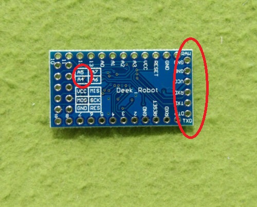
1. Make sure you source the correct Pro Mini board, that looks similar to the one in the photos below. It features an ATmega328 clocked at 16MHz.


5. Solder the 2 jumper bridges according to the OLED display you are going to use.


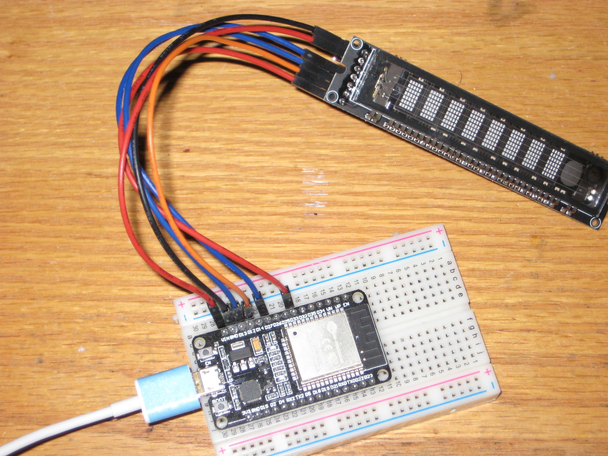
In the process of expanding the family of supported displays for the WiFiChron clock, I found this amazing VFD module on aliexpress:

It has an SPI interface, it is powered by 5V, character set is defined and stored internally.
A quick search produced a sketch and documentation for the driver, PT6302.
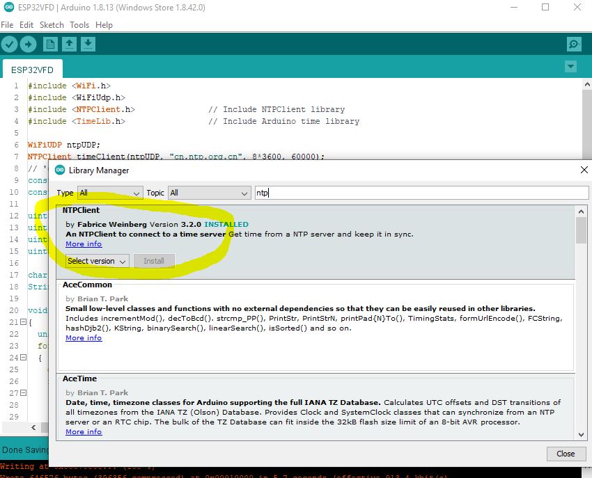
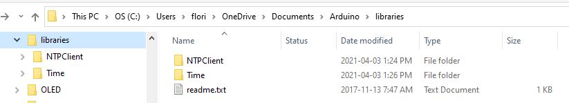
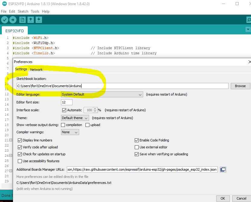
According to the PCB silkscreen, the VFD module is powered by 5V, but the signals are 3V3. (The 30V required by the VFD glass itself is made by the on-board switching mode power supply, so no need to worry about generating high voltage externally.) An ESP32 board would be the perfect candidate to control this display. Luckily, the found sketch was also written for ESP32, so all I had to do was compile and upload using Arduino IDE 1.8.13. The only problem was that my IDE installation did not show ESP32 boards anymore, even though I used it once previously. Therefore, I had to re-visit the whole setup process once again. This time I am documenting it, to save on any future effort. So here are the steps:


#include <WiFi.h>
#include <WiFiUdp.h>
#include <NTPClient.h>
#include <TimeLib.h>

WiFiUDP ntpUDP;
NTPClient timeClient(ntpUDP, "cn.ntp.org.cn", 8*3600, 60000);
const char *ssid     = "<wifinet>";
const char *password = "<password>";

uint8_t din   = 33; // DA
uint8_t clk   = 12; //23; // CK
uint8_t cs    = 13; //19; // CS
uint8_t Reset = 27; //22; // RS

char *str_time = "00:00:00";
String format_time = "00:00:00";

void write_6302(unsigned char w_data)
{
  unsigned char i;
  for (i = 0; i < 8; i++)
  {
    digitalWrite(clk, LOW);
    if ( (w_data & 0x01) == 0x01)
    {
      digitalWrite(din, HIGH);
    }
    else
    {
      digitalWrite(din, LOW);
    }
    w_data >>= 1;
    digitalWrite(clk, HIGH);
  }
}

void VFD_cmd(unsigned char command)
{
  digitalWrite(cs, LOW);
  write_6302(command);
  digitalWrite(cs, HIGH);
  delayMicroseconds(5);
}

void S1201_show(void)
{
  digitalWrite(cs, LOW);
  write_6302(0xe8);
  digitalWrite(cs, HIGH);
}

void VFD_init()
{
  // set number of characters for display;
  digitalWrite(cs, LOW);
  write_6302(0xe0);
  delayMicroseconds(5);
  write_6302(0x07);  // 8 chars;
  digitalWrite(cs, HIGH);
  delayMicroseconds(5);

  // set brightness;
  digitalWrite(cs, LOW);
  write_6302(0xe4);
  delayMicroseconds(5);
  write_6302(0x33); // level 255 (max);
  digitalWrite(cs, HIGH);
  delayMicroseconds(5);
}

void S1201_WriteOneChar(unsigned char x, unsigned char chr)
{
  digitalWrite(cs, LOW);
  write_6302(0x20 + x);
  write_6302(chr + 0x30);
  digitalWrite(cs, HIGH);
  S1201_show();
}

void S1201_WriteStr(unsigned char x, char *str)
{
  digitalWrite(cs, LOW);
  write_6302(0x20 + x);
  while (*str)
  {
    write_6302(*str); // ascii
    str++;
  }
  digitalWrite(cs, HIGH);
  S1201_show();
}

void setup()
{
  WiFi.begin(ssid, password);
  Serial.begin(115200);
  Serial.print("Connecting.");
  while ( WiFi.status() != WL_CONNECTED ) {
    delay(500);
    Serial.print(".");
  }
  Serial.println("connected");

  timeClient.begin();

  pinMode(clk, OUTPUT);
  pinMode(din, OUTPUT);
  pinMode(cs, OUTPUT);
  pinMode(Reset, OUTPUT);
  digitalWrite(Reset, LOW);
  delayMicroseconds(5);
  digitalWrite(Reset, HIGH);
  VFD_init();
}

void loop()
{
  timeClient.update();
  format_time = timeClient.getFormattedTime();
  char *str_time = &format_time[0];
  S1201_WriteStr(0, str_time);
  Serial.println(timeClient.getFormattedTime());
  delay(1000);
}
In the world of 16-segment displays, Klais-16 is the biggest I have seen, at about 8cm (3") character height. Multiple displays can be daisy-chained and controlled through serial communication (1 pin, TX). It is open source and available to buy on Tindie at the very reasonable price of US$15 a piece.
The biggest challenge was mechanical, particularly, finding a way to mount the 8 individual displays. Let me explain. I received the displays as ready-to-use (assembled, programmed and tested) products. I did not expected to dis-assemble them (not even partially) in order to mount them. The two mounting methods described in the documentation (using 15mm and 20mm profiles, respectively) ask for just that, basically to cut the original plastic rivets and, eventually, to replace them with (your own) M3 screws when fixing them to the rails. (I actually started going along with either described method until I realized I did not want to open them up). The easiest solution I found in the end was to use 1/2" x 1/2" L-profile, as shown below. For this, I only cut the middle rivets and used the holes to screw each individual display to the rails.


The software support consists in adding one class, DisplaySoftSerial.cpp, shown below.
#include <Arduino.h>
#include <SoftwareSerial.h>
#include "DisplaySoftSerial.h"

SoftwareSerial ss(7, 2);	// RX not used; TX=2;

//******************************************************************
//
void Display_t::setup()
{
  ss.begin(19200);
}

//******************************************************************
// draw the 8 characters on the screen;
//
void Display_t::writeDisplay(char* displayBuffer)
{
  char reverseBuffer[9] = {0};

  for (byte i=0; i<9; i++)
  {
    reverseBuffer[i] = (displayBuffer[7-i]);
  }
  ss.write(reverseBuffer);
}

//*******************************************************************
// brightness level is number between 0 and 7, 0 being the brightest;
//
void Display_t::setBrightness(uint8_t brightness)
{
  // cannot do;
}

//*******************************************************************
//
void Display_t::reset()
{
}


